Managing Common-Mode Current in an Offline Converter
Transformer currents between isolated domains are a common source of EMC issues. A simple, properly placed component is cheap insurance.
5/19/2026
Including a safety-rated Y-capacitor across the isolation boundary of an offline power supply is a standard technique for mitigating radiated emissions. These components provide a controlled return path for high frequency noise by bridging the primary and secondary grounds. However, schematics must be supported by proper low-inductance routing.
In this 2-layer open source design, the secondary side uses a solid reference plane, which properly bounds high-frequency return currents. The designer follows best practice by using a Y-capacitor across the primary and secondary grounds, but primary-side layout compromises the EMC strategy.
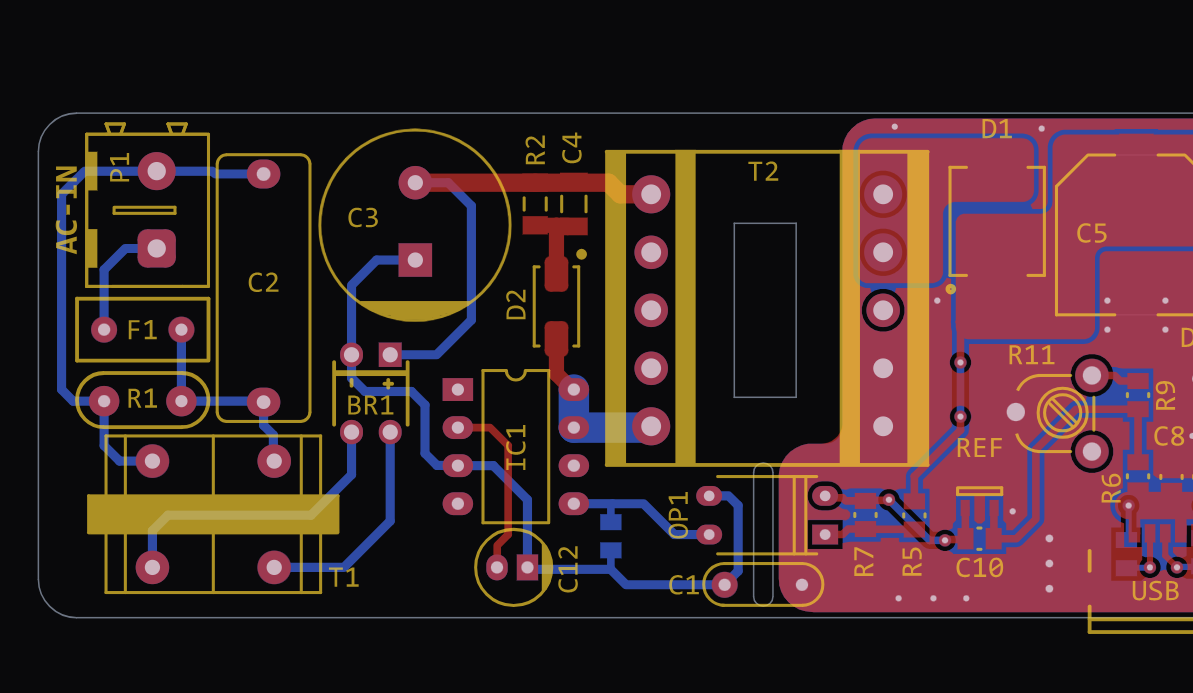
Here is the physics of why this fails:
• Transformer Parasitics: Isolated transformers inherently contain inter-winding capacitance between the primary and secondary coils, which acts as a coupling path for common-mode noise.
• Common-Mode Injection: During switching transitions, the high slew-rate voltage (high dv/dt) at the primary-side switch node generates displacement currents. These currents couple directly across the transformer's parasitic capacitance to the secondary side.
• Loop Inductance: The designer included a Y-capacitor to shunt these common-mode currents back to the primary ground. However, the capacitor is routed using a long trace back to the primary return. This physical loop area, combined with the intrinsic Equivalent Series Inductance (ESL) of the capacitor, creates a high total loop inductance.
• LC Resonance: A capacitor only acts as a capacitor up to its Self-Resonant Frequency (SRF). The added inductance of this layout drastically lowers the SRF. At high frequencies, the circuit stops acting as a capacitor and behaves like an inductor (Z = jwL).
• Cable Antennas: Faced with a high-impedance path, the common-mode current is forced to flow on the surrounding copper, potentially out onto attached external cables, and capacitively couple back to Earth Ground. This uncontrolled Earth Ground return loop turns the external cables into antennas, becoming a dominant source of radiated emissions.
Effective EMC design requires intentional layout decisions that complement the schematic.
Need this level of analysis for your next board?
Get in touch with our experts to book a consultation.